|
<< Click to Display Table of Contents >> Key Systems
|
  
|
Important: The following instructions pertain to the upgraded version of SITEMASTER 200. In this version, you can add and generate your own Key Systems, and the program supports most other brands and system types. In the Standard version of SITEMASTER 200, you don't have a Key Systems Screen. However, Schlage and Falcon system types are already preloaded. When you import your registered key systems from Allegion, you will be able to select your correct system type. Your Key Number and Cylinder/Core records will be added to both the Key Numbers and Cylinders Screens, and you can sort these records by system type.
You can create a Key System from a Manufacturer's System that you have added or use one of the pre-loaded ones such as Schlage Obverse Family 6 Pin or Schlage Everest B Family A2 7 Pin. Then create the system's Key Numbers and Cylinder/Cores. This is accomplished using one of the program's wizards such as the Create System Keys Wizard (The Combinator).
This topic includes:
Important: The program can import key systems from Schlage's Key Records Department (Schlage and Falcon). See Data Utilities > Importing Allegion Factory Key Systems.
The program allows you to create new key systems very quickly, and you can easily produce up to a six-level system for any Manufacturer's System that you've already set up in the program. Most one and two step systems are supported but there may be limitations with some specialized systems. When creating system keys and cylinder/cores, the program follows the guidelines of the Door Hardware Institute. If you have used these guidelines to create existing systems in the past for your customers, then you may be able to reproduce those existing systems with this program. After you create system key numbers and cylinder/cores you can assign them to customers' rooms and doors using other room and door wizards in the program. See Create Rooms Wizard.
Important: The process of using Wizards to create keys, cylinder/cores, rooms, and doors is the quickest and most efficient way to load your data into Sitemaster 200®. This topic discusses using the Create System Keys Wizard (The Combinator) for producing systems and loading keys and cylinders. If you can't use this wizard to load your records, then there is another wizard that loads your keys and cylinders simultaneously. This wizard works best when you need to type in the records that you want to add. See Add Key Numbers and Cylinders Wizard.
The program affords you a great deal of flexibility when creating key systems. You can create 2 to 6-Level systems all at once or create smaller partitions (legs) of a system in order to expand the system over time. Before you create your system keys and cylinder/cores you work with a KBA (Key Bitting Array) Screen in order to verify and even modify the key progressions that will be built. The program allows you to manipulate the KBA so that you may fully control the end result.
To Open the Key Systems Screen:
1. Click the Key Systems icon an the Main Button Bar.
2. The Key Systems Screen opens in the expanded view allowing you to Add or Look Up records. You may also access reports, exit from the Key Systems Screen, or change the mode of the screen. The buttons that appear with gray text are inactive and not available in this mode.
3. The Client lookup field is the default, but you may click on any of the Field Column Names, such as TMK, to look up records by that name.
4. Click on the Mode button to contract the Primary Record List to the left and display the record fields on the right.
Help with > Adding Records
1. Click on the Add button on the Key Systems screen.
2. Type in or select a Manufacturer's System. You must create the Manufacturer's System before you can assign it to a Key System. Schlage and Falcon types are preloaded.See Manufacturer's Systems.
3. Type in the name of the Client that you are assigning to the Key System. See field descriptions below.
4. Type in the Bitting (cuts) of the TMK (Top Master Key).
Note: The Create System Keys button will remain disabled until the information above is entered.
5. Type in a Sidebar or Angles into the fields provided if the system uses Keys/Cylinders that contain these features. For angles, this would be the angles for the cylinder chambers such as LCCRCR and not an angle code number.
6. For SFIC (Small Format Interchangeable Core) cylinders type in the Control Key(s) bitting. If you want to combine more than one control key, enter multiple keys by separating the control keys with commas and no spaces.
7. Click on the Save button to store the record or Cancel to abort the add.
8. The System Master Keys list is a Secondary Record List that displays all the master keys that have been created for the selected Key System.
9. Click on the Open Folder button on the System Master Keys list to jump to the Key Number Screen that displays all of the system keys for the selected Key System. To learn how to work with key numbers and key information screens, see Key Numbers.
See Managing Key Systems.
Field Descriptions of the Key Systems Screen:
Manufacturer's System: Create Key Systems based on a particular manufacturer's system type that applies to the keys and cylinders. Schlage systems are preloaded into the program but you can add most pin tumbler systems and create new ones that come out in the future. To learn how to add and work with Manufacturers' Systems, see Manufacturer's System.
Client: This is the customer who is assigned to the key system or the name of your key system. The Client field could be the name of a customer, department, building, or whatever designation that pertains to the key system. The Client field is not unique, so that you may have multiple key systems that pertain to the same client. For example, a customer has a Schlage Obverse .015" System and a newer Everest System.
TMK: This is the bitting (cuts) of the Top Master Key of the key system. The program will create lower-level masters and change keys based on the bitting of the TMK and your expansion specification.
TMK Symbol: This is the Symbol that you assign to your key system's TMK such as GGM, A, B, or whatever applies. The program generates Key Number and Cylinder/Core symbols based on standard key coding methods and will apply that symbolism to the different levels of keys.
Sidebar: Some systems such as Schlage Primus use a sidebar feature that's incorporated into the key blanks and cylinders. Enter the sidebar designation into the Sidebar field as a reference.
Angles: Some systems use an angle feature that's incorporated into the keys and cylinders. Enter the bitting angle designations such as LCCRCR.
Control Key Bitting: For a SFIC (Small Format Interchangeable Core) system, enter the control key(s) bitting into the field. The program will master SFIC cylinders with multiple control keys. If this is the case, enter the control keys bittings separated by commas and without any spaces (i.e., 6945611,6945631).
System Master Keys (list): This list and Secondary Record List display the master keys that have been created within the selected Key System. The master keys are displayed after they are created using the Create System Keys Wizard. The fields of this list include Keyway, Key Number, Symbol, Level, Bitting, and Description. As with any Secondary Record List, you may re-sort the list by clicking on any of the Field Column Names such as Level or Bitting. See Looking Up Key System Information.
To Edit and Delete Records:
Once you have records added, you can edit or delete the records as well as the linked information associated with those records. Editing and deleting records affect any parent-child relationships of those records. To learn about editing and deleting records, see Editing Records or Deleting Records.
To Look Up Records:
The program's interface provides you with an extremely efficient way to look up and sort records and to find linked record information. To learn how to look up records, see Looking Up Records.
To Access Reports:
Click on the Reports button on the record information screen or click on the pull down Reports Menu at the top of the Main Menu. To learn about the reports for this topic, see Reports.
The Add Key Numbers and Cylinders Wizard
This Wizard allows you to simultaneously add multiple key numbers and cylinder/cores to your Key System by typing them in. It's the go to method when you can't generate an existing key system, import your key system, or when you don't have complete information about your system. There is a dedicated topic for this feature. Click here to learn about this important feature.
The Create System Keys Wizard (The Combinator)
The Create System Keys button on the Key Systems Screen starts a program wizard for creating and loading Key Numbers and Cylinder/Core records that fall under the selected Key System. The primary function of the Create System Keys Wizard is to provide you with an extremely efficient method to load your customers' keys and cylinders into the program. This wizard requires only two screens to set up and to build program-assigned or custom-designed key systems.
To use this wizard, start by telling the program how many levels of keying you want and designate keyways, starting symbols, the quantities of master keys at each level, and the quantity of change keys under level one. This process defines your expansion specification. The program then produces a Key Bitting Array (KBA) screen that is based on the TMK bitting that was entered for the Key System and by the specifications that were already defined for the linked Manufacturer's System. The program allows you to change the Key Bitting Array for Sequence of Progression (SOP), the bitting numbers entered by the program, the bitting number order within each chamber, and the number of chambers that are allocated to master keys.
Important: This wizard uses Standard Key Coding Symbolism as recommended and outlined by the Door Hardware Institute (DHI). This wizard creates key numbers and combinated cores, so it's not used for generating unassigned bitting progressions.
Quick Start to Produce a Sample Key System
The Create System Keys Wizard is easy to use with a good working knowledge of master keying. You are in total control of just how simple or how complex your key systems are designed and executed. For many of you who just wish to produce straightforward key systems that take seconds to generate, follow along with the following example:
First you set up and add the information about the Key System:
1. On the Key Systems Screen, click on the Add button.
2. On the Manufacturer's System field, click on the Binoculars button. This displays the Manufacturer's Find Screen.
3. Click on the Find All button that displays all of the Manufacturer's Systems that have already been set up.
4. Select the Schlage Obverse Family 6 Pin. You may double-click on the record to select it, or click on it once and press the Accept button on the screen. This takes you back to the Key Systems Screen where the Manufacturer's System has been filled in by the program.
5. In the Client field, type in a name of one of your clients (customer or department) or just type in the word Test.
6. In the TMK field, type in the bitting (cuts) of a Top Master Key that you would like to try or type in 112722 for this exercise.
7. In the TMK Symbol field, type in the Symbol of your TMK or the symbol A as the practice symbol.
Note: The Create System Keys button will remain disabled until the information above is entered.
8. Press the Save button on the top left corner of the Key Systems Screen.
9. Notice that the TMK and Client name are added to the list on the left. Additionally, the Create System Keys button is now active.
Next, define the size and design (Expansion Specification) of your system as well as the symbolism that you want to use:
10. Press the Create System Keys button.
11. A screen that we refer to as the "Levels" screen is displayed. At this time, change the number in the Levels field to the number 3 and press the Enter key on your keyboard. We will produce a 3-Level system.
12. Look for the field on the left called "Level 2: Keyway" and move to the right of that field to the "Number of Masters" field that's on the same line. Change the number of masters for this field to 2. You're telling the Program that you want to produce 2 Master Keys at level 2.
Note: You can use your TAB key to go from field to field, or you can click your mouse directly inside any field.
13. In the "Number of Change Keys" field, type in the number 64. For each one of the Master Keys at level 2, you will be producing 64 change keys.
14. Click the NEXT button on the "Levels" screen. This displays the "KBA" (Key Bitting Array) screen.
15.You may modify the settings on the "KBA" screen, but for this exercise just press the Build Key System button at the bottom of the screen.
16. A "List of Progressions" preview screen is displayed that can be used to review the information before committing to the new system.
17. A small button bar called "Print Preview" allows you to print out the system keys, go forward or back to other pages, or to zoom in or out. There's also an icon button of an Open Door that's used to generate the new system.
Finally, validate the system and generate the keys and cylinder/cores:
18. Press the Open Door button on the Print Preview button bar. When you're asked if you want to save these Key Numbers and commit to the system, click on the YES button.
19. The Program starts to generate the Key Numbers, Symbols, and Cylinder/Cores. The process takes about 7 to 10 seconds for this 3-Level System. Click the OK button when the program tells you that the Key System creation is complete.
20. Congratulations, you've generated a 3-Level System consisting of a TMK called "A," with 2 Masters called "AA" and AB," and 64 Change Keys under each master.
21. Click on the Exit button on the "KBA" screen to return back to the Key Systems Screen. Displayed in the System Master Keys list are the three master keys A, AA, and AB that you just created.
22. Click on the Key Number List button on the top of the Key Systems Screen. This displays the Key Numbers List that contains all of the Change Keys that you've just created.
23. Click on the Cylinders List button at the top of the Key System Screen. This displays all of the Cylinder/Cores that you will later use to assign to your customer's rooms and doors.
24. Now, you may be wondering what you'll do with all of these keys and cylinders that were just created for this practice session. Well, let's just delete them!
Important: You can practice creating key systems and delete them afterwards. Make sure that you don't delete a key system that's in use. When you delete a Key System in this program, it deletes all of the key and cylinder information. This means that once you start to issue keys and cylinders to rooms and people, you should consider the ramifications of deleting the key system that's linked to those records. See Deleting Records.
25. On the Key Systems Screen, select the Key System that you want to delete, such as this practice system, and press the Delete button at the top of the screen.
Fundamentals of the Create System Keys Wizard (The "Combinator")
Important: To get the most out of the Create System Keys Wizard, you'll need to have a good working knowledge of Master Keying and be familiar with standard key coding methods. You use both the "Levels" screen and the "KBA" screen to set up and then build your system. You can build a complete system, or build out the system as you go. The wizard can be additive, so that you can create a new leg of the system each time you use it. Each time you build a system leg, the leg is symmetrical because of the symmetrical expansion specification. You can build different legs with different key quantities and with different levels of keying for each leg. This is how you produce asymmetrical systems. The Combinator will prevent you from creating duplicate bittings (keyway + bitting) but it will not stop you from creating system interchange or unintentional cross-keying. This means that you have to pay close attention to what you're doing when using the Combinator feature.
Both the Levels screen and the KBA screen "remember" how you set them up. After you build a system, the next time you use the wizard for the same system, the program displays the previous Number of Levels, Keyways, Expansion Specification, Starting Symbols, and the KBA setup that was used. The Combinator continues to remember the information for the highest levels of keying that were built.
Important: If you build a smaller leg to an existing system with fewer levels of keying than before, the Combinator does not remember this information. Instead, it remembers the information from the highest levels of keying that was previously built. However, if you continue to build out your system within the highest levels of keying used, the Combinator will continue to remember the information.
The key symbols that are assigned by the Create System Keys Wizard follow the guidelines of the Door Hardware Institute (DHI).
The Create System Keys Wizard (The Combinator) uses Standard Key Coding symbolism to generate key symbols. These standards are also followed by the Door Hardware Institute (DHI). The program produces two to six levels of keying.
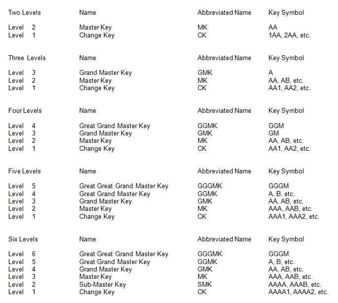
NOTE: 1) If you have an asymmetrical type system, you use the Combinator to run out each symmetrical leg (one at a time). The symmetrical legs can have different key quantities and different levels of keying. 2) There may also be workarounds for producing systems that may vary slightly from Standard Key Coding. These workarounds are not fully explained in this document, and may not be supported in future versions of the software.
On the Levels screen, the Number of Levels that you assign and the Number of Keys at each level of keying (Expansion Specification) determines how the program divides the key on the KBA screen. Another way to put this, is how the program allocates the master key and change key bitting progressions to chambers. For example, if you're working with a Schlage Everest Family system and you ask for four levels of keying with four Grand Masters at level three, the program will allocate only one chamber in the KBA for level three masters. This is because the program only needs to allocate a single chamber to meet your requirement. However, if you ask for five Grand Masters at level three the program is then forced to allocate two chambers for level three masters.
When using the Combinator to create only a portion of your key system, you may want to think ahead in order to plan for expansion and to divide the key (KBA) properly from the beginning. For example, you only need four Grand Masters now but eventually you may need eight. This means that the KBA will need to have two chambers assigned to level three. You can do this manually on the KBA screen if you have an available chamber (level 0) to re-allocate. See Changing the Level of an Available Chamber. You can also use the Combinator to help you to divide the key for future expansion.
Let's say that you'll need eight Grand Masters all together but right now you only want to produce four. First, set the Number of Keys at level three to be eight (See Fig. 1). When you go to the KBA screen you'll see that two chambers are assigned to level three (See Fig. 2). Click on the Back button to return to the Levels screen and change the number of Grand Masters at level three from eight to four (See Fig. 3). Now, when you go to the KBA screen, you'll see that two chambers are assigned to level three but the KBA is set up to produce only four Grand Masters at this time (See Fig. 4).

This is one of the ways that the Combinator remembers, and this can be applied to the different levels of keying. If you need to reset the KBA so that it stops remembering the previous key divisions, simply exit the Combinator. When you come back in, the wizard will either remember the setup of the system that you had previously built, or it will display the default, two levels of keying, if nothing has been built.
Important: If you happen to intentionally delete all of the keys in an existing key system, when you use the Combinator the next time for this system, it will still remember the setup from the last time. If you can't set up the Combinator the way that you want because of how the key is divided, simply add this key system (Add button) to the program again. The Combinator is then set to its default settings. You can delete the old empty system if you like.
1. After you have added a Key System, click on the Create System Keys button on the Key Systems Screen.
This displays the "Create Key Systems - Levels" Screen where you set up your expansion specification. The program displays two levels of keying as the default, but if you change the levels and build a new system, then that Number of Levels becomes the default setting the next time you work with this system. Key System (Client's Name) and TMK (Bitting) are already filled in from the previous Key Systems Screen.
2. In the Number of Levels field, type in the levels of keying for the new system or system expansion. You may enter the levels of 2 through 6. The screen will re-adjust itself to the number of levels that you've entered.
3. Select a Keyway by clicking the Down Arrow on the Keyway field for the TMK. The keyways that you may select are predefined by the Manufacturer's System that is assigned to this key system. If Manufacturers come out with new keyways in the future that pertain to the system, you will be able to add those keyways.
Important: At this particular point in the wizard, the program cannot check the relationships of multisectional keyways. If you are assigning multiple keyways, make sure that the relationships are correct because if you make an entry mistake, the program will produce the system that way!
4. Type in or select a keyway for the next highest level and do the same for any additional levels if they exist. This may be the same keyway as the TMK or may be different if you are working with a multisectional system.
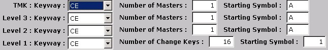
5. In the Number of Masters fields, type in the quantity of Master Keys that you want to create at each level. For example, if you enter 5 Masters at Level 3 and then 4 Masters at Level 2, the program will create 4 level-2 Masters under each of the 5 level-3 Masters. This produces a total of 20 level-2 Masters.
6. In the Starting Symbol fields, type in a starting symbol that you want to create at each level. The program uses your TMK symbol at the top level as the default but you may change the symbol.
Important: The Starting Symbol field (top right) for the TMK may be edited but does not change the original symbol of the TMK. Instead, this Starting Symbol field is used to create symbols that do not begin with the symbol of the TMK. For example, if your TMK's symbol is "GGM " and you enter the Starting Symbol as "A," all of the Key Numbers that follow will start with "A" instead of "GGM."
7. In the Number of Change Keys field, type in the quantity of change keys that you want to create under each Master Key at level two.
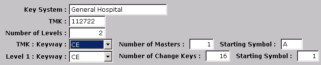
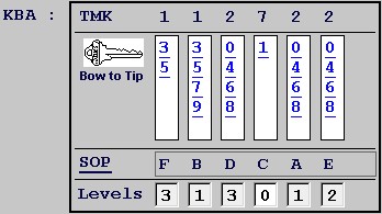
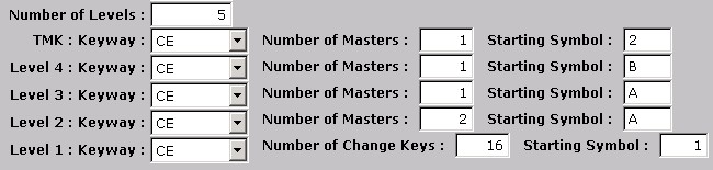
Figure 1 - Four Levels of Keying for General Hospital

Important: The example illustrated in Figure 1 is set up to build a four-level system. The program uses symmetrical expansion so you will get the same number of theoretical combinations under each level. In this example, only a portion of the possible Masters at level three are being requested. The quantities of Masters and Change Keys that you may request are limited to the rules of master keying. How you "divide the key" will govern the possible key quantities. The program will alert you if your key quantities exceed the limit of the expansion specification.
If you were to continue to create the system as illustrated in Figure 1, you would produce the following system keys (theoretical quantities shown):
A = TMK
AA = 4-Pin Master
AAA = 3-Pin Master, AAA01 - AAA64 = Change Keys
AAB = 3-Pin Master, AAB01 - AAB64 = Change Keys
AAC = 3-Pin Master, AAC01 - AAC64 = Change Keys
AAD = 3-Pin Master, AAD01 - AAD64 = Change Keys
AB = 4-Pin Master
ABA = 3-Pin Master, ABA01 - ABA64 = Change Keys
ABB = 3-Pin Master, ABB01 - ABB64 = Change Keys
ABC = 3-Pin Master, ABC01 - ABC64 = Change Keys
ABD = 3-Pin Master, ABD01 - ABD64 = Change Keys
AC = 4-Pin Master
ACA = 3-Pin Master, ACA01 - ACA64 = Change Keys
ACB = 3-Pin Master, ACB01 - ACB64 = Change Keys
ACC = 3-Pin Master, ACC01 - ACC64 = Change Keys
ACD = 3-Pin Master, ACD01 - ACD64 = Change Keys
AD = 4-Pin Master
ADA = 3-Pin Master, ADA01 - ADA64 = Change Keys
ADB = 3-Pin Master, ADB01 - ADB64 = Change Keys
ADC = 3-Pin Master, ADC01 - ADC64 = Change Keys
ADD = 3-Pin Master, ADD01 - ADD64 = Change Keys
AE = 4-Pin Master
AEA = 3-Pin Master, AEA01 - AEA64 = Change Keys
AEB = 3-Pin Master, AEB01 - AEA64 = Change Keys
AEC = 3-Pin Master, AEC01 - AEC64 = Change Keys
AED = 3-Pin Master, AED01 - AED64 = Change Keys
When comparing the requested setup in Figure 1 with the system keys listed above, the following relationships apply:
1. The 5 Masters requested at Level 3 = AA, AB, AC, AD, AE.
2. The 4 Masters requested at Level 2 produces 4 Masters under each Level-3 Master (symmetrical expansion) or 24, 3-Pin Masters (4 Level-2 Masters X 6 Level-3 Masters).
3. The 64 Change Keys requested at Level 1 create 64 theoretical change keys under each 3-Pin Master or 1,536 theoretical Change Keys (64 changes X 24 Level-2 Masters).
8. Click the Next button on the Create Key Systems - Levels Screen to display the Create Key Systems - KBA Screen.
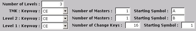
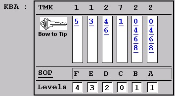
Figure 2 - The Key Bitting Array for General Hospital

Important:
The program produces a default Key Bitting Array (KBA) based on the bitting of the TMK. The example that has been illustrated in Figure 2 shows the bitting progressions for all of the change keys and defines the chambers that have been allocated to the different key levels. We can see that chambers 4, 5, and 6 (Levels = 1) have been fully expanded and are assigned to progress change keys in accordance with the Sequence of Progression (SOP). The four Level-2 (3-pin) Masters that were requested are shown in chamber 3 (Levels = 2). Chambers 1 and 2 are reserved for the five Level-3 (4-pin) Masters that were requested (Levels = 3). Even though the program displays eight possible 4-pin Masters (2X4), it will only generate the five 4-pin Masters that were requested.
The program automatically removes MACS violations after you build your system. This is why, for example, you may only get 53 actual change keys when you asked for 64 theoreticals in your expansion specification. The program will also remove MACS violations at your master key levels, so if you want to get your full specification of master keys, you will need to check the bitting numbers for the master chambers in the KBA. If you build the system without checking, your system will generate but you may not get, your full expansion specification. Simply, check the master chambers (Levels that are equal or greater than 2) for MACS violations. If you see a violation, change the bitting number(s) to remove the violation(s). If you can't adjust the bitting numbers to take care of this, then the system you're working with is not capable of meeting your specification for actual key quantities. See Changing the Bitting Order and Bitting Number.
9. The fields above the KBA include Key System, TMK, Angles, Sidebar, and Number of Levels in System. This information is automatically displayed by the program from where it was entered on the Key Systems Screen.
10. The Control Keys field below the KBA, for a SFIC (Small Format Interchangeable Core) system, will display the Control Key(s) that were entered on the Key Systems Screen. You may also edit this field to change or add a Control Key(s) that will be used to build your cylinder/cores. The program will master key multiple Control Key Bittings to provide you with more flexibility when working with SFIC systems.
11. The Keys per Key Number field lets you enter a quantity of keys that the program will create for each different key in the system. Additionally, the Check Box field, Create Keys as Serialized Keys will be prechecked if the Manufacturer's System Screen for this Key System was checked for key serialization. You have the option to deslect the check box on the KBA screen if you don't want the new system's keys serialized. The key numbers, quantities, and serial numbers for every key are maintained in the Key Numbers Screen. See Key Numbers.
Very Important: Once you create your key numbers as either serialized or non-serialized keys, you can't change the status of these keys once they're issued to personnel. Once issued, the keys would first have to be returned by personnel, the status changed, and then re-issued.
12. The Rotation Style that the program uses by default is the Total Position Progression method. You can defeat, in part, this method by modifying the KBA. See Defeating Total Position Progression.
13. The Create Key Number Based on: selection box allows you to select between Symbol, Blind Sequence, Blind Code, Bitting, and Reverse Bitting methods for key numbering. Selecting a method will then number your keys using that style. For example, selecting the Symbol method will produce key numbers with standard DHI symbols. The method you choose is usually based on the key numbering style that will be used for stamping numbers on keys.
Symbol - This method numbers your Key Numbers with the same designations as the Key Symbols assigned by the program.
Blind Sequence - This produces sequentially numbered keys, where each key number is unique from every other key number (i.e., 00001, 00002, 00003). When adding key numbers manually using this method, you will need to figure out the next blind sequence number(s). The program will not generate these numbers for you when manually adding key numbers.
The Start Value - This field is used to assign the starting sequence number when using the Blind Sequence or Blind Code methods. For example, you want to match the sequencing for key numbers that already exist. Type in the blind sequence Start Value to begin the sequence of numbering. Once master keys are assigned their blind sequence numbers, the masters retain those numbers when you use the wizard again to expand your system. For the Blind Code method below, the Start Value is the numeric equivalent of the alpha-numeric blind code number.
Important: When using the Start Value feature, if you create a gap in your sequence numbers (i.e., 00001 to 00014...GAP...00027 to 00053), the program does not fill in the missing numbers when you use the feature next time. Instead, it looks for the highest number (i.e., 00053) and continues. Additionally, if you fill in the gap later, make sure that the Number of Change Keys on the Create System Keys-Levels Screen does not exceed the gap quantity. For example, if the gap is between 00014 and 00027, then your Starting Symbol would be 00015 and the Number of Change Keys would be twelve (i.e., 00015 to 00026). If you exceed the gap quantity, then the program will duplicate blind sequence numbers based on the difference. In the previous example, if your starting symbol is 00015 and the Number of Change Keys is fourteen instead of twelve, you will get the two duplicate key number records of 00027 and 00028.
Blind Code - This method produces alphanumeric key numbers where each key number produced is unique from every other key number regardless of Key System, Keyway, or Key Symbol. As additional keys are created, the key numbers' character length will increase. However, compared with a numeric-only sequencing, this alphanumeric method will always produce key numbers with fewer characters to stamp on keys. If you select this method, you will need to use the Create System Keys Wizard for creating all of your blind codes. This is because when adding key numbers manually, the program does not generate the blind code numbers for you.
Important: When adding key numbers manually, the program does not figure out the next key number to use. This is normally not a problem if your keys are numbered as Symbols, Bittings, or Reverse Bittings. However, it may be difficult for you to figure out what the next Blind Code or Blind Sequence should be. Keep this in mind before choosing the Blind Code or Blind Sequence methods of key numbering.
Bitting - The program assigns the bittings (cuts) of the keys as the key numbers.
Reverse Bitting - The program reverses the bittings (cuts) of the keys and assigns these as the key numbers.
14. Current Master Keys List - This list displays any master keys that have already been added to the existing system. This can be used as a guide to determine what's already been used in the system, and what's still available for expansion. This list is displayed on both the Levels and KBA acreens.
15. Click on the Build Key System button to create your keys and Cylinder/Codes, or press the Back button to go back to the Create Key Systems - Levels Screen. The Back button allows you to rethink your KBA and go back to the expansion specification to perform any modifications.
16. When you click on the Build Key System button, the program checks to see if you are creating any duplicate bittings (Keyway + Bitting) that already exist in your system(s). If you are, the program will display, "Duplicate bittings found. Please try again."
This is to prevent you from creating systems that will interchange with one another. Check the bittings that you are trying to progress against the ones listed in the Key Numbers Screen and adjust your KBA to produce unique ones.
Important: If you use the program's default progression assignments on the KBA screen and build a system from these, you won't be able to repeat those progressions again. The program will display the "Duplicate bittings found" message and you will need to modify the KBA in order to build a system of unique bittings. Additionally, if you add new Key Numbers manually to the program and assign bittings, the program will not allow you to build a new key system if any of the bittings that would be progressed match the bittings of those key numbers. When building key systems, the program will not "skip over" existing key numbers. Unique bittings for key numbers are defined as the Keyway plus the Bitting (i.e., CE + 123456).
17. If you choose to build the key system, a preview report will display what is named the List of Progressions.

The purpose of this preview report is to allow you to review the key progressions before making a final commitment to the system. You may also print out the report for review or hard copy. The fields of the List of Progressions report includes Keyway, Symbol, Key Number, Bitting, Level, Parent, Sidebar and Angles. The List of Progressions above is displaying just a part of a single page of many pages of this sample Key System.
Note: Under the Reports Menu > Key System Listings, there is a List of Progressions report.
18. Use the Print Preview button bar to select the report's pages, look up a page, change the size of the page, print the report, or continue to build the system's keys and Cylinder/Cores.
When you pass your mouse pointer over any of the button icons on the Print Preview button bar, text appears and displays the function of the button. The inner right and left arrows select the next or previous page. The outer arrows select the first or last page of the document. The stacked pages icon lets you go to a specific page in the document. Click on the down arrow of the 100% field to increase or reduce the page view by a selected percentage. The printer icon is for printing the document. The open door icon is used to build and save your system.
19. Click on the Open Door icon. The program asks you if you want to save the keys and commit to the system.
20. Click Yes to generate the Key Numbers and Cylinder/Cores or No to abort the operation. Your computer and the size of the key system being generated determine the time that it takes to create the system keys and cylinder/cores. To create the sample 4-level system above that consists of 1,536 keys and cylinder/cores takes approximately 50 seconds with a Pentium 4 computer.
Important: You can experiment with the Create System Keys Wizard all you want and even commit to building the system keys. This will help you to get a better feel and understanding of this wizard tool. You can quickly set up a practice Key System and then run the Create System Keys Wizard. Go through the entire process to create the keys and then view the results on the Key Systems Screen. At any time, you can Delete the entire Key System by selecting it on the Key Systems Screen and clicking on the Delete button. When you are working with real records, you need to be careful when using the Delete feature. See Deleting Records.
After you build your Key Systems, depending on the number of change keys requested, you may notice extra zeros within your Key Symbols. At least, this may seem to be a deviation from the standard coding method that you may be used to. For example, the symbol AB11 may show up as AB011 or there may be additional zeros included in other symbols. This was done intentionally so that the program could properly sort your Symbols when looking them up. If the program was set up to generate Symbols the standard way, then when you sorted your Symbols you would get, for example:
AB108
AB109
AB11
AB110
AB111
For this reason, we have the program generate these zeros for sorting and lookup purposes. As far as your own symbology is concerned, you may ignore these extra zeros and exclude them if you stamp Symbols on your keys. The Door Hardware Institute accepts this method of key coding.
Looking Up Key System Information
Once you have created system keys and cylinder/cores using the Create System Keys Wizard, there are three different lists accessed from the Key Systems Screen that provide you with all of the information you need about these records. These lists help you to maintain and manage your key system information and can be helpful when making decisions about system expansion.
The System Master Keys list is used to display all of the different master keys that have already been created under a key system. Use this list as a guide when you want to expand the key system and to decide what new symbols and bittings to generate. The list displays all of the master keys created at all the different key levels and includes the symbols and bittings that have been used. This screen is also a Secondary Records List so you may re-sort the list by clicking on any Field Column Name such as Symbol or Bitting to help you to analyze the sections of a system that are available for expansion.
1. Click on the Key Systems button on the Key Systems Screen to display the System Master Keys list.
2. This screen displays the Keyway, Key Number, Symbol, Level, Bitting, and Description for each Master Key in the list.
3. Click on the Open Folder button on this screen to jump to the Key Information Screen for the Master Keys under the selected Key System. This screen is actually the Key Numbers Screen that pertains specifically to this key system. To learn more about working with Key Numbers, see Key Numbers.
4. Click on the Edit button on the Key Information Screen to change any information about a selected Master Key. This is also where you type in the Description of a master key that will be displayed in the System Master Keys list. Be careful with the information about a Master Key that you edit because it will affect any other records that are linked to it.
5. Click the Save button to record the changes and then click on the Exit button to return back to the Key Systems Screen.
Idea: When you need to expand a system, first search for a new compatible symbol to use by reviewing the System Master Keys list for symbols that have already been assigned. You can click on the "Symbol" Field Column Name to re-sort the list by Symbol. Figure out the new Symbol for the highest level Master, under the TMK, that you're going to use for the new expansion specification. Go through this same process to figure out the new Bitting for this Master Key. Then use the Create System Keys Wizard to create the new Key Numbers and Cylinder/Codes. Afterwards, the Master Keys that you created will be displayed in the System Master Keys list.
1. Click on the Key Number List button on the Key Systems Screen. This changes the mode of the screen.
2. The selected Key System is displayed but you may pick another key system to view by clicking on its record in the Primary Record List on the left side of the screen.
3. The Key Number List displays all of the keys that have been created for the selected Key System. The fields included on this list are Keyway, Symbol, Bitting, Building, Room, and Description. This list displays the keys that have been assigned to rooms as well as those that are available to be assigned (unassigned).
Idea: You can use the Key Number List to determine how many keys are left to assign to rooms across the various key symbols (partitions) within a customer's system. Under each master key symbol you can view the available change key symbols that are not assigned to any rooms. This can help you to determine when you need to talk to your customer about expanding their key system or rekeying their facility. As you rekey rooms, some of the existing change keys will lose their room assignments. The symbols of these keys will reappear as unassigned keys in the Key Number List. If you have access to key issuance information, you will be able to make decisions about recycling your old keys back into circulation. If you select an unassigned key on the Key Number List and click on the Open Folder button, you can quickly view the key issuance history of that key. This will let you decide if the key is safe to recycle back into the customer's system.
1. Click on the Cylinder List button on the Key Systems Screen. This changes the mode of the screen.
2. The Cylinder List on the Key Systems Screen displays all of the Cylinder/Core codes that have been created under the selected Key System. The fields included on this list are Keyway, Cylinder/Core, Building, and Room. All the Cylinder/Cores that are assigned and unassigned to rooms are displayed in the list.
3. Select any Cylinder/Core record in the Cylinder List by clicking on it. Click on the Open Folder button on the Cylinder List to jump to the Cylinder Information Screen about that Cylinder/Core record. To learn how to work with cylinders and with cylinder information screens, see Cylinders.
4. On the Cylinder Information Screen, you can view all of the keys that operate this cylinder from the Operated By Keys list. You can also click on the Pinning Screen or Print Pinning Chart buttons as well. Any of these options will provide you with the Bittings for all the keys that operate a particular cylinder.
The Current Master Keys List appears on the Create System Keys - Levels Screen and on the KBA Screen. The list displays the master keys that have already been created for the selected system. The list appears on these two screens as an aid to help you expand your existing system. For example, the list displays the symbols and bittings of the master keys that have been generated. This can help you to decide what new symbols and bitting progressions to use for the next leg of your system.
Adding New Keys to a Key System
When you are working within an existing key system, the program allows you to manually add new keys that will be linked and displayed within that key system. Normally, you would use the Create System Keys Wizard or the Add Key Numbers and Cylinders Wizard to accomplish this. This method provides you with a manual method to create a new key without automatically creating a cylinder/core record. Later, you can add a new cylinder/core record using the Cylinders Screen and key (pin) that cylinder up to the new keys that you've added. The keys and the cylinders that you create this way stay linked to the key system where they were created.
1. Click on the Open Folder button on the Key Number List to jump to the Key Number List Information Screen for the keys pertaining to the selected Key System.
2. Click on the Add button.
Help with > Adding Key Numbers
3. Type in and look up all of the information for the new Key Number.
4. Click on the Save button. The new Key Number is added to the Key Numbers List of that key system.
When adding Key Numbers this way, it's a good idea to be mindful of the symbolism that you use and, of course, the bitting of the keys. If you duplicate the keyway plus the bitting, the program will display a message that this has happened. When adding keys to key systems, the program will not allow duplicate bittings across the same keyways regardless of the method you use to create the keys.
To Add or Modify Cylinders to Key Systems
When you use the Create System Keys Wizard to produce your cylinder/core records, all of the new cylinders are pinned to individual change keys and to the master keys that were assigned to the upper levels of keying. You can take these existing Cylinder/Core records and modify the keys that operate them. Depending on how you make the modifications in the program will decide whether or not the new cylinder is included within the Key System or not. For example, you may create a new Cylinder/Core record that uses an existing change key from a key system but is not pinned to any of the master keys from that system. The program lets you decide if you want to include this Cylinder/Core within the system or set it up outside of the system. The advantage of adding the cylinder/core to the system is that the cylinder will be displayed in the Cylinders List of that system.
1. Click on the Cylinders List button at the top of the Key Systems Screen.
2. On the Cylinder List, click on the Open folder button. This displays the Cylinder List Information subscreen for the selected Key System.
3. You may either Add a new cylinder from scratch or you may Copy an existing cylinder and then modify it.
1. Click on the Add button and then type in and look up the information that applies to the new cylinder/core.
2. Click on the Save button. The Add Master Key and Add Operated By buttons are now active.
3. Use these buttons to add the operating keys to the new cylinder that appear in the Operating By Keys List.
4. The new cylinder now appears in the Cylinders List of the selected Key System.
To Modify an Existing Cylinder to Create a New One:
1. Click on the Cylinders List button at the top of the Key Systems Screen.
2. On the Cylinder List, click on the Open folder button. This displays the Cylinder List Information subscreen for the selected Key System.
3. Click on the Copy This Cylinder button. This duplicates the cylinder/core and allows you to rename it in order to reflect your modifications. You then can modify the operating keys of the cylinder.
4. Type in the information for the new Cylinder and add/remove any operating and/or master keys to the cylinder. The keys appear in the Operated By Keys list.
5. Click on the Save button to store the new cylinder record.
6. The new Cylinder/Core will appear in the Cylinders List that is linked to the Key Systems Screen.
To Add a New Cylinder that falls outside of a Key System, see Cylinders: To Manually Add a New Cylinder
A Word about the Expansion Specification
Important: We suggest that when you initially create the keys for a multilevel system or leg of the system, that you consider entering the maximum quantity of theoreticals that you will actually need for your change key positions (Level 1). For example, with a typical two-step, 6 pin system, instead of "1 - 2 - 3 - 27" enter "1 - 2 - 3 - 64." Taking this approach prevents you from having to perform another expansion specification to produce additional keys and cylinder/cores. The program keeps your unassigned (extra) keys on-hand to be assigned at a later date, so that creating all of them instead of only the ones you need right now may be more convenient and save you time.
Designing and Customizing Key Systems
The following examples are used to demonstrate the different features in the Create System Keys Wizard that allows you to specify your system and change the default settings that the program applies. With the program, you can create fully expanded systems that you can then assign to your customers' spaces as necessary. You may also create the parts of a system as you need them, building the segments or what we refer to as partitions as you go. We recommend that you always start with an expansion specification that will produce more than enough keys than a system will ever need. Additionally, you can reproduce most systems that are already in use by adjusting these settings. The main purpose of the Create System Keys Wizard is to load your keys and cylinders into the program. This means that this wizard is a tool to help you load both new and pre-existing customer systems.
Modifying the Expansion Specification (The Create Key Systems - Levels Screen)
Help with > To Create System Keys above.
1. On the Key Systems Screen, you would click on the Create System Keys button to go to the Create Key Systems - Levels Screen.
Figure 1 - The program displays two levels as the initial default.
2. The Levels screen displays a default 2-level system. We will change the Number of Levels from 2 to 4 for this example.
3. The right side of the screen displays the Starting Symbols for each Level including the TMK, which is actually Level 4 in this example. The program uses the symbol, for example "A," based on the symbol assigned to the TMK. You can change this Symbol.
Figure 2 - Number of Levels changed from 2 to 4.
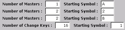
4. Let's first analyze the expansion specification. If we were to build this system as is, we would get a single Level - 3 Master (AA) with a single Level- 2 Master (AAA) under it. The program would produce 16 change keys in all that would be numbered AAA01 to AAA16.
Figure 2 =
A
AA
AAA
AAA01 - AAA16
5. If you change the Number of Masters for Level 3 from 1 to 2 and the Number of Masters for Level 2 from 1 to 2, the expansion specification changes.
Figure 3 - Number of Masters for Levels 2 and 3 changed from 1 to 2. The new expansion specification is "1 - 2 - 2 - 16."
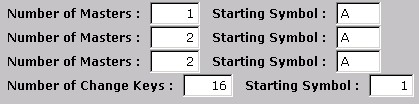
Figure 3 =
A
AA
AAA
AAA01 - AAA16
AAB
AAB01 - AAB16
AB
ABA
ABA01 - ABA16
ABB
ABB01 - ABB16
6. The program allows you to change the Starting Symbols so that you may reproduce the symbolism of an existing system or set a new one up to your own design. We will modify the Starting Symbols.
7. With your mouse, you would highlight the Starting Symbol field for the Level 3 Masters and type in the number 2. You would then do the same for the Starting Symbol field for the Level 2 Masters and type in the letter B.
Figure 4 - Modifying the Starting Symbols.
This would produce the following symbolism:
Figure 4 =
A
A2
A2B
A2B01 - A2B16
A2C
A2C01 - A2C16
A3
A3B
A3B01 - A3B16
A3C
A3C01 - A3C16
8. In the following example, we will work with the same Key System but create a new expansion specification in order to create special symbol progressions. For example, you want to progress combinations for change keys that fall under the "A3" Master from the system symbols.
9. On the Key Systems Screen, select the system to expand and click on the Create System Keys button.
Figure 5 - Adding Special Symbol Change Keys to an existing system.

In this example, we will be adding 10 change keys (A301 to A310) that are allocated to operate with the TMK and A3 Masters only. This expansion specification would produce the following key symbols that would be incorporated into the system shown in Figure 4:
Figure 5 =
A
A2
A2B
A2B01 - A2B16
A2C
A2C01 - A2C16
A3
A301 - A310 - These new keys would be created from the expansion specification in Figure 5.
A3B
A3B01 - A3B16
A3C
A3C01 - A3C16
Once you allow the program to build these new keys, the keys would show up on the Key Numbers List (Key Systems Screen) for this particular Key System. This is a method of adding keys to an existing system. Before you can actually build these keys, however, you'll have to modify the KBA Screen in order to mathematically "fit" these new keys into your existing system. Below, are additional modification techniques that allow you to "fit" keys into existing systems or to specify the design of new systems.
1. You may assign different keyways to your different Levels by selecting the Down Arrow on the Keyway field for any Level.
2. The example, Figure 6 is based on the Schlage Classic .015" Manufacturer's System that has been preassigned to this Key System. You must first assign the Keyways to a Manufacturer's System before you can select them on this screen. See Manufacturer's Systems.
Figure 6 - Assigning different Keyways at different levels for multi sectional systems.
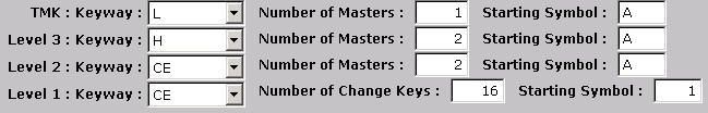
With this setup, the program will assign these Keyways to the Key Numbers:
Figure 6 =
| L | = A |
| H | = AA |
| CE | = AAA |
| CE | = AAA01 - AAA16 |
| CE | = AAB |
| CE | = AAB01 - AAB16 |
| H | = AB |
| CE | = ABA |
| CE | = ABA01 - ABA16 |
| CE | = ABB |
| CE | = ABB01 - ABB16 |
Dividing the Key with the Number of Masters Fields
By leaving the Number of Levels constant and increasing the Number of Masters at selected levels, you can omit higher-level masters that the program may produce by default. These higher-level Masters that are "squeezed-out" of the specification still exist as theoreticals and will operate the cylinders if they are made.
1. Using the example in Figure 6 (above), the program will produce the following bittings for the Master Keys by default:
Figure 6 = "1 - 2 - 2 - 16" (expansion specification)
| A | = 112722 |
| AA | = 312722 |
| AAA | = 332722 |
| AAB | = 352722 |
| AB | = 512722 |
| ABA | = 532722 |
| ABB | = 552722 |
2. Looking at the bitting assignments for AA (312722) and AB (512722) and considering future thoughts for the expansion of this system, you notice that you are limited to the number of level-3 Masters that can be created with this current setup. The program only needs to allocate the first chamber to meet the specification of only 2 Masters at Level 3. Your site has five buildings on it and you would like to assign a Master to each building. As your site grows, you will need more Masters, so you want the program to use at least two chambers for these Masters. This could theoretically produce up to sixteen 4-Pin Masters instead of the four 5-pin Masters that the program has allocated by default.
3. By changing the Number of Masters at Level 3 from 2 to 5 for five buildings, for example, the program is forced to allocate two chambers to accomplish this. This is because you can only progress 4 numbers in a single chamber (two step) so at least two chambers are needed to create 5 Masters.
Important: Even though the 5-Pin Masters (312722 and 512722) still exist in theory, you have squeezed them out of the expansion specification by limiting the Number of Levels to 4 and increasing the number of Level 3 Masters to 5. If you wanted to keep the 5-Pin Masters and also have all of the 4-Pin, Level-3 Masters, you would change the Number of Levels for this expansion specification from 4 to 5.
4. At this time, you also decide to increase the number of level-2 Masters to 4.
Figure 7 - Increasing the Number of Masters. The expansion specification is now "1 - 5 - 4 - 16."
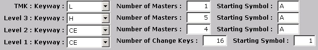
Figure 7 shows the new expansion specification. The program would now produce the following 4-Pin Master Keys:
Figure 7 = "1 - 5 - 4 - 16" (expansion specification)
AA = 332722
AB = 352722
AC = 372722
AD = 392722
AE = 532722
Instead of the first chamber being used for the level-3 Masters, we now have chambers one and two being used. The Level 2 Masters have also been divided-down and reduced to 3-Pin Masters.
Modifying the Key Bitting Array (The Create Key Systems - KBA Screen)
Help with > To Create System Keys above.
Changing the Bitting Number Order and Bitting Number
Important: These two features allow you to customize the KBA so that you can specify bitting combinations to either reproduce existing systems, add to existing systems, or to produce new systems. For example, set up your levels and symbolism to create the symbols that match those of an existing system. Then, adjust the KBA so that the bitting combinations within each level get assigned to the right symbols for the existing system. See also, Reproducing an Existing System below.
1. Following the example from Figure 7, click on the Next button on the Create System Keys - Levels Screen to go to the Create System Keys - KBA Screen.
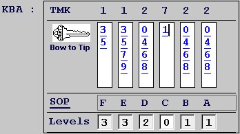
Figure 8 - KBA for a 4 Level System.

2. The program assigns a numbering sequence in each chamber that starts with the next highest bitting number based off of the TMK. Let's say, you happen to prefer a numbering sequence of lowest to highest number in each chamber. You decide to change the bitting numbering order for the third, fifth, and sixth chambers that is currently 4, 6, 8, and 0.
3. Click on the first number (4) in the third chamber. A text curser appears to the left of the number. On your keyboard, type the first replacement number. In this example, the first replacement number would be "0." As soon as you type the "0," the program automatically moves the cursor down to the next number. This means that after you set the cursor on the first number at the top of the chamber, all you have to do is to type the replacement numbers (0,4,6,8) one after the next to change the chamber. Repeat this process for chambers five and six.
Figure 9 - Reordering the numbers in the third, fifth, and sixth chambers.

4. Figure 9 shows the bitting numbers reordered for chambers 3, 5, and 6. As you further study the KBA, you realize that for every change key that will be created, it will receive a deep number 9 cut in the fourth chamber. Not only is this a problem with keys breaking constantly but such a deep cut will cause you to lose more keys to MACS violations.
5. To change a bitting number in any chamber, click on that number in the chamber and then type in the replacement number.
Figure 10 - Changing the bitting number in chamber 4.
In this example for Figure 10, the 9 in the fourth chamber is changed to a 1.
Changing the Sequence of Progression (SOP)
Important: If you're going to change the default Sequence of Progression, you should do this before using the other editing features on the KBA Screen. This is because when you manipulate the SOP, the program reverts back to its default settings for bitting number order and bitting number. As you change the sequence order, the program automatically adjusts each chamber for the parity of the TMK.
1. Using Figure 10 as the example, you start by clicking on the first sequence letter on the SOP line that you want to change.
2. For example, you would click on the "E" under chamber "2." This puts the text cursor to the left of the letter "E" and highlights the entire SOP field. We will type a "B" to change the chamber sequence. Then we will do the same for the fifth chamber by changing the "B" to an "A." Finally, we will change the "A" in chamber six to an "E." When you change the SOP make sure that you wind up using all of the letters "A" through "F" for a six pin system. If you know the sequencing of the entire SOP designation, you can click on the letter in the first chamber and type in all of the letters consecutively.
Figure 11 - Changing the Sequence of Progression and resetting the Bitting Number and Order to match Figure 10.
3. After you make your changes, you can press Enter, Tab, or just click your mouse on a blank area of the screen.
4. The Level numbers follow the new sequence of the chambers to help you keep track of the new SOP.
5. Once you're done changing the SOP, you may then proceed to edit the KBA using any of the other features.
Changing the Level of an Available Chamber
When you execute your expansion specification from the Create Key Systems - Levels Screen, the program divides the Key Bitting Array one chamber at a time until it fulfills your specification. In certain cases, there are chambers that are "available" because these chambers were not needed to be progressed by the program in order to meet your specification. Such chambers are indicated on the KBA Screen with Levels = 0. This situation usually occurs when you specify a system that is only partially expanded. By changing the level of one of these "0" chambers, you force the program to redivide the key so that additional chambers are allocated to your Masters or Change Keys. This also effectively reduces the Master Key(s) (i.e., 5-Pin to 4-Pin to 3-Pin) by dividing them down. This feature is similar to "Dividing the Key with the Number of Masters field" mentioned above, but with this feature you do not have to add additional masters to your expansion specification in order for the program to redivide the key.
We'll use a partially expanded 3-Level system to demonstrate this feature:
1. On the Create Key Systems - Levels Screen, the following expansion specification is set up:
Figure 12 - A partially expanded three level system.
If you glance at the right side of the screen for Figure 12, you can see by the Starting Symbols that the first change key produced will be AB1 (AB01).
2. Only 1 level-2 Master and 16 Change Keys have been specified to produce the following KBA screen in Figure 13:
Figure 13 - The KBA of a partially expanded three level system.
The program assigns the following bittings to the single Master Key and the first Change Key by default:
Figure 13 =
| A | = 112722 |
| AB | = 312722 (5-Pin Master) |
| AB01 | = 334944 |
3. You decide that you don't want to issue such a potentially high-level Master (AB) to your customer, so you want to divide-down the AB Master so that it is allocated another chamber by the program and reduced, for example, to a 4-Pin Master.
4. You would click in the first Levels field marked with a "0" (Figure 13), which is the one aligned with the second chamber. Change the number from "0" to "2."
Figure 14 - Changing the Level of a Chamber that equals zero.
5. This assigns the second chamber in Figure 14 to level 2, so now both the first and second chambers are allocated to level two. By doing this, the program would change the bitting of the AB Master when you generate the system:
Figure 14 =
| A | = 112722 |
| AB | = 332722 (4-Pin Master) |
AB01 = 334944
6. This method prevents the program from creating an additional upper level master (i.e., 312722) that is not desired. If you were to change the remaining "0" chambers to "2", you would wind up with: A = 112722, AB = 334922, and AB01 = 334944.
Defeating Total Position Progression
The program allows you to set a bitting progression number to the same cut as the TMK and to omit bitting progression numbers from the KBA. If you do this, keep in mind that the expansion specification that you set up on the Levels Screen may not be met for key quantities. To change the bitting progression number, simply highlight the cut in the KBA with your mouse and change it to match the corresponding TMK cut. To omit a bitting progression number, highlight that number with your mouse and press the Delete or Backspace key on your keyboard. When you build your key system, the program will create the new key numbers based on your KBA setup. As usual, the program will also remove any MACS violations.
Deleting Master Keys and Associated Cylinder/Cores
Important: The program uses a parent-child relationship for linking records. For this reason, if you delete a Master Key from the system, the program will also delete all of the associated Key Numbers and Cylinder/Core records that are linked to that master. We recommend that you do not delete any records unless you understand the consequences of doing so. With that said, deleting Master Keys may be used as a feature to fine-tune your Key Systems. For example, the program generates key systems symmetrically which may provide you with more master keys and change keys than you need. By allowing you to selectively delete master keys at any level, you can remove the portions of the system that you do not intend to use.
1. Look up and select the Master Key from the System Master Keys list on the Key Systems Screen.
2. This displays the information screen for the master key.
3. Click on the Delete button on the Key Number information screen. Note: You cannot delete a master key if it has been issued to personnel.
Adding Theoretical Masters After the System is Built
The Create System Keys Wizard does not create theoretical masters, such as row or block masters, because it only creates the actual key numbers that you set up and generate. There may be a situation after you've built your system for the need to implement a theoretical master. The program won't give you these keys so you will need to add them manually and then assign them to the cylinder/cores that they operate (optional).
Important: You can use the Combinator to produce fully expanded systems. One example, a 3-Level system with 64 page master with 64 change keys per page master. So, your entire system is expanded symmetrically. The common question, is where are my theoretical block and row masters, for example, and how do I add them when needed? The answer, is that you would add them using either method described below. This way, you can fully expand your system, and then insert the theoretical masters as required. You will have to figure out the bittings for those masters when you add them to your system, because the Combinator only produces actual and not theoretical masters.
Note: If you just add a new master to your key system as described below, the master will automatically be combinated into the cylinder/cores that it operates mathematically. The master will be displayed as an IM (Incidental Master) on the Pinning Screens, Pinning Charts, and some Cylinder Reports. If you take the additional step to mass-assign the master to the appropriate cylinder/core records as described below, then the master will be displayed as an operating key of the cylinder/cores. You must assign the new master key its proper bitting for it to show up as an IM (Incidental Master).
To Add and Mass-Assign a New Master to Cylinder/Cores
1. On the Key Systems Screen, click the Key Numbers List button.
2. Click the Open Folder button on the Key Numbers List.
3. Click the Add button on the Key Number List for Key System sub-screen.
4. Type in the information about the new Master and click Save. Don't forget to assign a Level of 2 or greater for the master.
The new master will now be displayed as an IM (Incidental Master) for all Cylinder/Cores that it mathematically operates. Take the next optional steps if you want to formally assign the master as an operating key for the Cylinder/Cores:
5. Click the Key Usage button.
6. Click the Binoculars button on the Key Also Operates List.
7. Look up and locate the cylinder/cores that the new master key will operate.
8. Select the cores and click the Accept button. You may also click the Select All button to check all cores in the list.
9. Click the Save button to store the records.
Reproducing an Existing System
Important: The program uses symmetrical expansion, which means that the number of theoretical combinations is the same under any level of master keys. If your system is asymmetrical by design, you will most likely need to execute more than one expansion specification within the same Key System record in order for you to assemble the different parts (partitions) of your system. The following example demonstrates how to use the Create System Keys Wizard to reproduce a key system that is made up of both symmetrical and asymmetrical partitions. Once you become familiar with the Create System Keys Wizard, you will be able to reproduce a key system like the one in Figure 1 in just a matter of minutes. Note: The flow chart is shown for illustration purposes and is not produced by the program.
Figure 1 - Reproducing an Asymmetrical System.
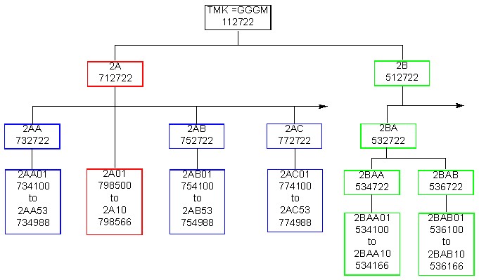
The System flow chart of Figure 1 represents a large but only partially expanded system. The flow chart has been broken down into three distinct color-coded partitions. Each partition will be used to set up a separate expansion specification. After the three expansion specifications are generated (blue, red, and green), the entire system will be created. Even though the system as a whole is asymmetrical in design, each of the three partitions is symmetrical unto itself. If you wanted to have different quantities of change keys under the level-2 Masters within each partition, you would have to divide those partitions again and perform additional expansion specifications for each unique leg. We suggest that you generate your change keys symmetrically with equal numbers under the same partition masters as demonstrated in the Figure 1 flow chart. This provides you with spare keys for future assignments.
1. The following displays the Create Key Systems - Levels and KBA Screens for setting up each color-coded partition. When you want to reproduce one of your own existing systems, you will need to collect the same type of information that is shown in the Figure 1 flow chart in order to produce your system and to validate the results. The keyway for Figure 1 is "CE." To learn how to manipulate the Create Key Systems - Levels and KBA Screens, see Designing and Customizing Key Systems.
Blue Partition
 |
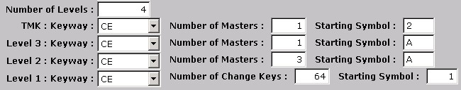
2. The Blue Partition of the Figure 1 flow chart represents a 4-Level system and would have a conventional expansion specification of "1 -1 - 3 - 64." This expansion specification can be recognized by looking at the Number of Masters fields from the top-down which is 1 - 1 - 3 - 64. When you compare this to the flow chart in Figure 1, keep in mind that the Blue Partition also incorporates the "2A" Master and TMK that make up the 4 levels.
Important: Instead of entering the Number of Change Keys as 53 as shown on the flow chart, a quantity of 64 (4X4X4) is entered instead. If we entered the quantity as 53 change keys, then we might not get 53 keys if there were losses to MACS. Instead, we will enter the next highest theoretical quantity of change keys, in each of the following examples, to ensure that the requested quantity of keys is satisfied after MACS violations are removed.
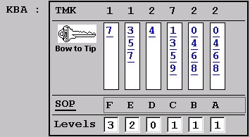
3. The KBA of the Blue Partition has been modified so that all progressed combinations will match those of the flow chart in Figure 1.
Red Partition

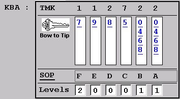
4. The Red Partition is an example of a Special Situation Symbol. In this example, change keys are created that fall directly under a higher level Master Key. This is a 3-Level partition of the system that includes the TMK to make up the three levels. A quantity of 16 (4X4) theoretical change keys has been requested in order to get the 10 change keys indicated on the flow chart after losses to MACS.
5. The KBA has been modified to match the bittings indicated in the Figure 1 flow chart.
Green Partition
6. The Green Partition contains 5 levels of keying with the addition of two 3-Pin Masters (2BAA and 2BAB) that don't exist in the other partitions of the system. The Starting Symbols have been set up to produce the first change key "2BAA1."
7. The KBA has been modified to match that of the flow chart.
8. After setting up the Expansion Specification and KBA for each partition (Blue, Red, and Green), you would click on the Build Key System button on the KBA screen to create the Key Numbers and Cylinder/Cores. The List of Progressions preview report that follows allows you to validate your keys and bitting combinations before you actually generate each partition. When you're satisfied with the results, you would click on the Open Door button on the Print Preview button bar. When asked by the program if you would like to save the Key Numbers and commit to the system, you would click on the Yes button. All of the key numbers created would show up in the Key Number List and all of the Cylinder/Cores would be displayed in the Cylinder List on the Key Systems Screen. Additionally, the Master Keys from all three partitions that were generated would be displayed on System Master Keys list on the Key Systems Screen.
We'll use the key system from above as an example of how to expand an existing system. From the Figure 1 flow chart, in Reproducing an Existing System, you can see that the Green Partition may be expanded to include additional 4-Pin Masters like "2BA." For this example, we will create an additional master called "2BB" and we will add an additional master level to this partition of the system. This new leg of the system will require 6 levels from the expansion specification.
Figure 1 - The system partition "2BB" is added to the system's flow chart.
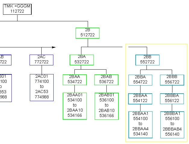
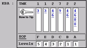
Figure 2 - The expansion specification for the new "2BB" partition.
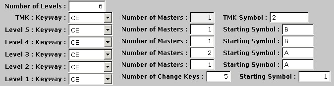
1. Comparing Figures 1 and 2, we "steer" the expansion specification "1 - 1 - 1 - 2 - 1 - 5" to only create this partition of the system. As shown in the flow chart and on the screen, the first change key of the new partition will be "2BBAA1." For each level 2 Master, there will be only 4 change keys created. Why did we ask for 5 change keys in the expansion specification instead of 4? In case there is a MACS violation, by requesting 5 keys the program is forced to allocate 2 chambers to produce change keys. This makes sure that we at least get the number of change keys that we request. An even better idea or practice would be to request 8 theoretical change keys so that we make sure that we'll get at least the 4 change keys if losses to MACS are high. This would also give us additional change keys for future assignment.
2. You would click on the Next button on the Create Key Systems - Levels Screen (Expansion Specification) to go to the Create Key systems - KBA Screen (KBA).
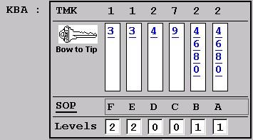
Figure 3 - The program produces the following KBA by default.
3. We need to change the program's default KBA to match the partition of the system that we're trying to create. From the flow chart and from Figure 2, we know that the first change key that will be progressed is "2BBAA1" and its bitting will be "554100." The method of progression is Total Position Progression so we can set up the top line in the KBA to match the bitting of the first change key.
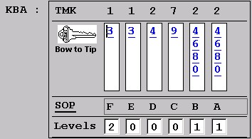
Figure 4 - Modifying the KBA to produce what we want.
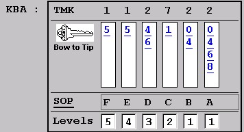
4. The bitting numbers in the first and second chambers are changed from 3-3 to 5-5 and the fourth chamber from 9 to 1. The bitting order numbers in the fifth chamber are changed from 4-6 to 0-4 and the ones in the sixth chamber from 4-6-8-0 to 0-4-6-8. The KBA is now set up to produce the new "2BB" partition.
5. When we click on the Build Key System button, the following List of Progressions is displayed for the new change keys:
Figure 5 - The List of Progressions validates that we've created the keys that we wanted.
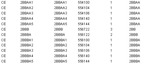
6. The program creates the 5 change keys under each 2-Pin Master.
Figure 6 - The new partition "2BB" is added to the system

7. The "2BB" partition is added to the Key System but we actually have five change keys each under the "2BBAA" and "2BBBA" master key.
Creating New Change Keys within an Existing System
The following is an example of how to use the Create System Keys Wizard to create any additional change keys that are unused theoreticals under a specific Master Key. If you have already progressed all the possible change keys under a master then this process won't help to create additional keys. This example also shows you how to work with the Key Number and Cylinder Lists of the Key Systems Screen in order to extract important information about your key system.
Important: In order to create additional change keys under an existing Master with this program, you will need to know the levels of keying that were used for that leg or partition of the system as well as the bitting of the last change key. This provides you with the information you need to set up the expansion specification and KBA to create the new change keys. The following example demonstrates a couple of different ways that you can use to extract this information from the program:
1. For example, if you wanted to create additional change keys and cylinder/cores to expand the "2AB" partition shown in the Figure 6 flow chart above, you would first acquire the levels and bitting information that you needed to set up for the new expansion specification and KBA. Out of the 64 theoreticals there were actually 53 change keys created after losses to MACS. The bitting of "2AB53" tells you how to modify the KBA that will be set up in order to create the additional change keys.
Figure 1 - Checking the last bitting progressed in the system's "2AB" partition.
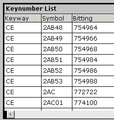
2. You would click on the Key Number List button on the Key Systems Screen to display the Key Number List. See Figure 1.
3. Sort the list by Symbol by clicking on the "Symbol" Field Column Name.
4. You would scroll down to the last change key symbol created in the series. In this example, the change key is 2AB53. The bitting for this key is 754988.
Let us say that we don't have the luxury of a flow chart to determine the levels of keying. With standard key coding methods the symbol of a change key can usually tell you the levels of keying. For example, the change key 2AB53 can be seen as 2 - A - B - 53 or 4 levels of keying. Another way to see this is 2 > 2A > 2AB > 2AB53. Another way you can extract the levels of keying is from the Cylinder/Core record:
5. Click on the Cylinder List button on the Key Systems Screen to display the Cylinder List.
6. You would then find and select the "2AB53" Cylinder/Core record on the list and double-click in the record.
7. This displays the Cylinder Information Screen for the "2AB53" cylinder.
8. The Operated By Keys list on the Cylinder Information Screen displays all the master keys that operate the cylinder as well as the TMK. You can use this information to determine the Levels of Keying for this particular cylinder. To print out a hard copy of this information as a reference, you can click on the Print Pin Chart button.
Figure 2 - This portion of a Pinning Chart displays the Bittings of all the Operating Keys for Cylinder/Core "2AB53."
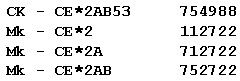
9. By reviewing these keys for the Cylinder/Core, we can extract the levels of keying.
10. You would now Exit back to the Key Systems Screen and click on the Create System Keys button to create the new expansion specification.
11. By looking at Figure 2, we can determine that there are 4 levels of keying (3 Masters + CK) and that the keyway for all keys is "CE." If any Operated By (OB) or Incidentals (In) show up, disregard them as "Levels." You now decide that you want to create additional change keys under the "2AB" 4-Pin Master Key. You've already got 53 keys created from the first 64 theoreticals and you know that there is a total of 256 theoretical change keys for a 4-Pin Master (4X4X4X4 = 256).
Figure 3 - A new Expansion Specification to produce the remaining Change Keys under the "2AB" Master.
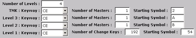
12. To determine and create all of the remaining change keys under the "2AB" Master, you just subtract the number of theoreticals that were already used from the total number of theoreticals. This would be: 256 (total) - 64 (used) = 192 (remaining).
13. The expansion specification in Figure 3 displays the setup to create the new Change Keys. You will have MACS losses so you won't get all of the keys that are requested. Looking at the Starting Symbols on the right side from the top-down, you can see that your first change key will be 2AB54. Whenever you use the Create Key Systems - Levels Screen (expansion specification), set up your Starting Symbols to show the first change key to generate. Doing so will produce the correct results. Notice that the Number of Masters are all set to "1." This is how you "steer" the program to create just the specified partition (2AB) and nothing more. Additional Master Keys will not be created because the Masters specified in Figure 3 already exist in this Key System (2, 2A, and 2AB).
14. Click on the Next button to go to the KBA Screen.
Figure 4 - The program produces this KBA by default.
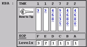
15. You need to change the KBA to match the new keys to be progressed.
Figure 5 - A properly set up KBA to create the remaining "2AB" change keys.
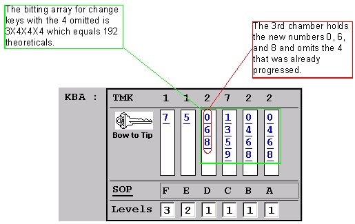
16. The program produces the KBA in Figure 4 by default. You adjust the KBA in order to produce the correct bittings for your new "2AB" series keys. First, you need to change the numbers in the first and second chambers from 3-3 to 7-5. The Change Keys "2AB01" through "2AB53" that are already created completely used up all of the "7-5-4" combinations to generate the 64 theoreticals. This means we leave out the 4 in the 3rd chamber to generate the rest of the change keys. To create your new keys, you change the 3rd chamber to progress only the remaining numbers (0, 6, and 8). This then omits the 4 that has already been created.
17. If you build these keys the List of Progressions would display the following:
Figure 6 - The List of Progressions for the new "2AB" change keys.
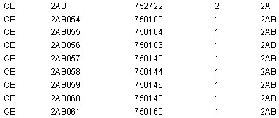
and continued...
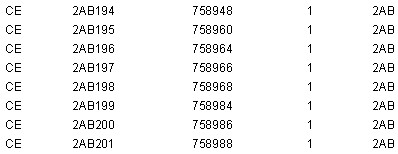
End
Out of 256 theoreticals you now have the 53 Change Keys 2AB01 - 2AB53 (original) and 2AB54 - 2AB201 (new). A total of 55 change keys were lost to MACS. When you create new system keys, we recommend that you request the full amount of theoreticals from the expansion specification at that time. The program keeps track of both assigned and unassigned keys, making it easier to rekey doors when the unassigned keys have already been created. Assigned keys are those that have been assigned to doors and the unassigned keys are the spare keys used for future rekeying.
18. A revised flow chart for the key system that we've been using as an example would now look like this:
Figure 7 - The revised System Flow Chart.

With the program, you can assign a Key System (TMK) to a Client, and any Client may have a Key System under a single TMK or multiple Key Systems under different TMKs or even under different Manufacturers' Systems. The program will track key interchange across the different systems under the same Manufacturer's System and even under different Manufacturers' Systems when they share compatible keyways. For example, a Classic Primus System that is integrated with a Classic Obverse system can display the interchange of the Primus keys with the Obverse cylinders.
Our recommendation is that you set up the methods that you are most comfortable with and the ones that are truly manageable and secure for your clients. Additionally, you can create practice systems utilizing the different setups and then delete these systems when you're done.
Setting Up Key Systems for Clients
To Set Up a Single Client with Single or Multiple TMKs
1. On the Key Systems Screen, click on the Add button.
2. Type in or select the client's Manufacturer's System and type in the Client's name.
3. Type in the TMK and any additional information as needed. See To Add a Key System.
4. Click on the Save button on the Key Systems Screen. The Client's record is displayed in the Primary Record List on the left.
5. Click on the Create System Keys button to begin the process of building the Client's Key System.
6. If the same Client has another TMK and/or Manufacturer's System, repeat steps 1 through 5.
The Client field is not unique so you may list multiple key systems for the same client. When doing this, make sure that you spell the name of the client the same way each time because the program won't check for you. You can always correct a mis-spelling using the Edit button.
7. If you add another Key System for the Client, then the Client is listed twice in the primary Key Systems Record List.
Figure 1 - A Client listed with two different Key Systems.
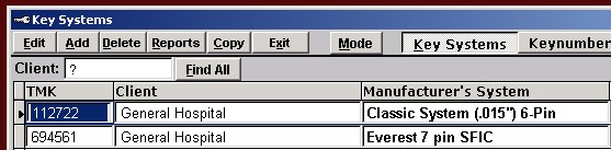
8. You can re-sort the Record List by clicking on any of the Field Column Names such as Manufacturer's System.
9. If you're working with a site that consists of multiple departments and/or buildings, or if you just want to apply names to your masters, then you can use the Description field on the System Master Keys list to assign those names to your Master Keys. See Looking Up Key System Information.
Figure 2 - Assigning Description Names to Master Keys.

To Set Up Multiple Client Descriptions under the Same TMK
This is really the same situation as shown in Figure 2, but instead of having departments under a site such as a College, the Description names could be the names of commercial businesses. Let's say you did the work for a building management company (the Client) that provided maintenance and services for its tenants. You can use the Description field to assign the names of the different commercial tenants to their master keys. See steps 1 through 9 above to set up the Key System.
Important: Once you have added a Key System(s) and created the system keys, you're now ready to assign Cylinder/Cores and keys to your site or to your customer's site. If the site uses fairly standardized hardware on its doors, you should consider adding this hardware to Products and then create Hardware Groups from these products. By doing this first, when you start to create room numbers, using the Create Rooms Wizard, you will be able to load the hardware to doors as you are making the Cylinder/Core and key assignments. See Products, Hardware Groups, Create Rooms Wizard.
Note: After you produce your Key System(s), you can create a variety of reports that contain helpful information to manage your system(s). Go to Reports > Key System Listings. In the Help Manual, go to the Reports topic to see samples of these reports.
Re-assigning Key Numbers and Cylinders to Another Key System
You may have a situation where you need to re-assign all, or a group of your key numbers and cylinders from one key system to another. For example, you loaded your key numbers from a previous version of SiteMaster and all of the keys and new cylinders were assigned to the Generic Key System in the newer version. The key numbers in your old version actually belonged to two different key systems, but now, all of your keys and cylinders are rostered under the single Generic Key System. You need to take a portion of your keys and cylinders and re-assign them to a new system(s).
To re-assign your key numbers:
1. On the Key Systems Screen, select the key system that you want to re-assign key numbers.
2. Click on the Key Number List button.
3. Click on the Edit button.
4. Click on the Binoculars button on the Key Number List. This opens a Key Number Find Screen.
5. Look up the Key Numbers or click the Find All button.
6. Click in the check boxes for the key number records that you want to re-assign to the selected key system.
7. The Select All button will select all of the key numbers.
8. Click on the Accept button.
To re-assign your cylinders:
1. On the Key Systems Screen, select the key system that you want to re-assign cylinders.
2. Click on the Cylinder List button.
3. Click on the Edit button.
4. Click on the Binoculars button on the Cylinder List. This opens a Cylinder Find Screen.
5. Look up the Cylinders or click the Find All button.
6. Click in the check boxes for the cylinder records that you want to re-assign to the selected key system.
7. The Select All button will select all of the cylinders.
8. Click on the Accept button.
Loading From a Previous Version of SiteMaster
When you load your system(s) from a previous or older version of SiteMaster (i.e., v.1.0 through v.2.84), your keys and new cylinders may get assigned to a "Generic" Manufacturer's System and/or a "Generic" Key System. A generic "KWY" may also be assigned to your keys as the keyway. This happens when this information was not created in your previous version of the program.
To change and/or sort your records to actual system and/or keyway assignments, see the following topic information:
1. Loading Data from an Older Version > Loading Key Numbers
2. Keyways > The Keyway Key Numbers and Keyway Cylinders sub-screen
3. Key Systems > Re-assigning Key Numbers and Cylinders to Another System
